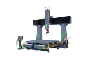
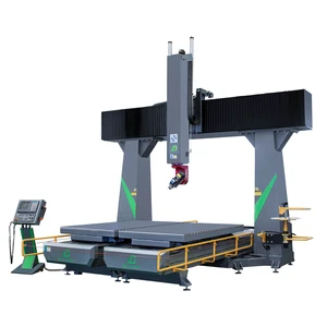
A 303 stainless steel spacer is turned complete in one cycle, so threads, grooves and cross holes keep their relationship to the turned datums. This page covers 303 stainless steel spacer produced for automotive: CNC turning with live tooling, sub-spindle back working and in-process gauging. Every unit is supplied to drawing rather than to a catalogue description, and Ø 40 mm × 200 mm is the starting point rather than the limit.
In practice the difficulty is rarely the nominal size. ±0.01 mm is held on the features that locate the part in the assembly, and the process is set up so that the first piece and the five hundredth measure the same way.
Specification
| Process | Cnc turning with live tooling, sub-spindle back working and in-process gauging |
|---|---|
| Material / configuration | 303 stainless steel |
| Size / capacity | Ø 40 mm × 200 mm |
| Tolerance | ±0.01 mm |
| Surface finish | as machined, Ra 0.8 µm or better |
| Application | spacer for automotive |
| Inspection | Dimensional report, material certificate, first article report on request |
| Lead time | 7–15 working days for samples, 3–4 weeks for production |
| Minimum order | 1 piece for prototypes, from 50 pieces for production pricing |
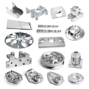
Manufacturing process
Production begins with a drawing and material review. Stock is certified, the operation sequence is fixed, and CNC turning with live tooling, sub-spindle back working and in-process gauging is carried out on equipment maintained to hold ±0.01 mm over a full shift, not just on a first piece.
Material is purchased against a certificate and checked on receipt, so the composition is known before any cutting starts. Work in progress is identified by part number and operation, and the finished parts are deburred, cleaned and protected before they leave the machine area.
Typical applications
Most of the work supplied in this category falls into the following examples.
- Motor and gearbox shafts.
- Pump and valve bushings.
- Sensor mounting collars.
- Hydraulic adaptors and fittings.
- Roller and idler spindles.
Quality control and documentation
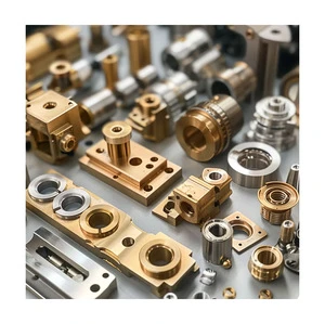
Inspection is not a final formality. Dimensions are checked during the cycle and again at the end, so drift is corrected while there is still stock to remove.
Material certificates to EN 10204 3.1, dimensional reports and first article inspection reports are issued with the shipment where the application requires them. Calibration dates and measurement uncertainty are recorded alongside every result.
Ordering, lead time and packaging
Orders start from a single piece. Samples are quoted from the 3D model, and production pricing follows once quantity, finishing and inspection are agreed.
Frequently asked questions
Can milled features be included?
Yes. Live tooling and a C-axis produce flats, cross holes and keyways in the same cycle, which keeps their relationship to the turned datums rather than adding a second setup tolerance.
What tolerance is normal for turned diameters?
±0.01 mm is routine and ±0.005 mm is achievable on small diameters with a finishing pass and in-process gauging. Concentricity is usually held within 0.02 mm.
Do you keep tooling and programmes for repeat orders?
Fixtures, tool lists and verified CAM programmes are retained for the life of the part number, so a repeat release runs on the same setup as the first batch without a new proving run.
Send the drawing or the 3D model for a quotation. Include material, quantity, tolerance and finish, and a detailed quote with lead time is returned within one working day.