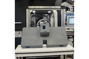
A Pneumatic Fixture is the difference between a part that measures correctly once and a part that measures correctly every time. The Pneumatic Fixture described here is built in a cast iron body with machined datums and developed for aerospace structural machining. fixture design around drawing datums with clamped, verified location is applied with tool life and the maintenance interval agreed before building starts.
The parts that matter most are the interfaces: bores, sealing faces, threads and mounting patterns. Those are held to repeatability within 0.01 mm, verified against the drawing, and recorded before anything is packed.
Specification
| Process | Fixture design around drawing datums with clamped, verified location |
|---|---|
| Material / configuration | a cast iron body with machined datums |
| Size / capacity | part sizes from 20 to 1200 mm |
| Tolerance | repeatability within 0.01 mm |
| Surface finish | hardened locating pads and clamps |
| Application | pneumatic fixture for aerospace structural machining |
| Inspection | Dimensional report, material certificate, first article report on request |
| Lead time | 7–15 working days for samples, 3–4 weeks for production |
| Minimum order | 1 piece for prototypes, from 50 pieces for production pricing |
Manufacturing process
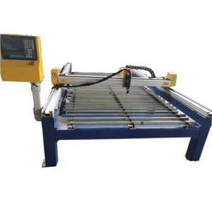
The operation sequence is decided before the first chip is cut: roughing to leave even stock, semi-finishing, then fixture design around drawing datums with clamped, verified location as the final operation. That order is what keeps repeatability within 0.01 mm stable as the batch runs and the machine warms up.
Material is purchased against a certificate and checked on receipt, so the composition is known before any cutting starts. Work in progress is identified by part number and operation, and the finished parts are deburred, cleaned and protected before they leave the machine area.
Typical applications
Most of the work supplied in this category falls into the following examples.
- Holding thin wall housings for machining.
- Locating parts for robotic welding.
- Assembly of instrument sub-assemblies.
- Drilling hole patterns in repeat batches.
- Inspection of critical interfaces.
Quality control and documentation
Every batch is measured against the drawing with calibrated equipment, and results are recorded against the part number rather than kept on a scrap of paper.
Material certificates to EN 10204 3.1, dimensional reports and first article inspection reports are issued with the shipment where the application requires them. Calibration dates and measurement uncertainty are recorded alongside every result.
Ordering, lead time and packaging
Quotations are returned within one working day of a complete drawing package. Lead time is quoted from drawing approval, not from the date of enquiry.
Frequently asked questions
Why build a dedicated fixture instead of using a vice?
A vice locates the part approximately and needs indicating every time. A fixture locates from the drawing datums, so parts are loaded correctly in seconds and measure the same way.
Are fixtures kept between orders?
Yes. Fixtures are retained for the life of the part number, which is why a repeat batch runs on the same setup as the first one with no re-proving.
Do you keep tooling and programmes for repeat orders?
Fixtures, tool lists and verified CAM programmes are retained for the life of the part number, so a repeat release runs on the same setup as the first batch without a new proving run.
To discuss pneumatic fixture requirements, send the model and the drawing with the quantities required. Feedback on manufacturability is given free of charge before any order is placed.