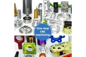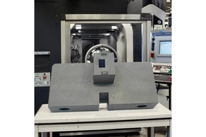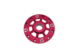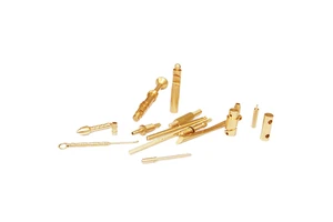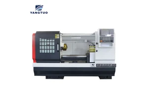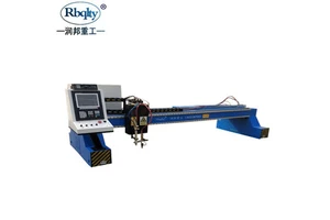
A Bending and Forming Tool turns flat strip into finished parts at rates no machining process matches, once a design and a volume justify the investment. This page covers a Bending and Forming Tool built in carbide inserts at high wear points for automotive body and bracket work work: tool design with strip layout, wire cut detail and tryout on press. The tool is designed around the part and the volume rather than copied from a previous job.
In practice the difficulty is rarely the nominal size. ±0.05 mm is held on the features that locate the part in the assembly, and the process is set up so that the first piece and the five hundredth measure the same way.
Specification
| Process | Tool design with strip layout, wire cut detail and tryout on press |
|---|---|
| Material / configuration | carbide inserts at high wear points |
| Size / capacity | material thickness from 0.2 to 6 mm |
| Tolerance | ±0.05 mm |
| Surface finish | deburred and hardened tool surfaces |
| Application | bending and forming tool for automotive body and bracket work |
| Inspection | Dimensional report, material certificate, first article report on request |
| Lead time | 7–15 working days for samples, 3–4 weeks for production |
| Minimum order | 1 piece for prototypes, from 50 pieces for production pricing |
Manufacturing process
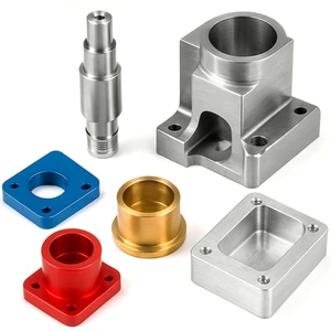
Production begins with a drawing and material review. Stock is certified, the operation sequence is fixed, and tool design with strip layout, wire cut detail and tryout on press is carried out on equipment maintained to hold ±0.05 mm over a full shift, not just on a first piece.
Material is purchased against a certificate and checked on receipt, so the composition is known before any cutting starts. Work in progress is identified by part number and operation, and the finished parts are deburred, cleaned and protected before they leave the machine area.
Typical applications
Most of the work supplied in this category falls into the following examples.
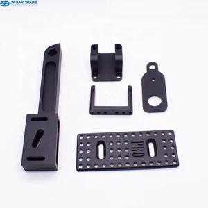
- Brackets and mounting plates.
- Terminals and contacts.
- Shielding cans and frames.
- Washers and shims.
- Hinges and clips.
Quality control and documentation
Inspection is not a final formality. Dimensions are checked during the cycle and again at the end, so drift is corrected while there is still stock to remove.
Material certificates to EN 10204 3.1, dimensional reports and first article inspection reports are issued with the shipment where the application requires them. Calibration dates and measurement uncertainty are recorded alongside every result.
Ordering, lead time and packaging
Orders start from a single piece. Samples are quoted from the 3D model, and production pricing follows once quantity, finishing and inspection are agreed.
Frequently asked questions
When is a progressive die worth the cost?
Above roughly 50,000 parts a year. Below that, laser cutting and bending usually costs less in total, even though the piece part price is higher.
How is burr formation controlled?
By correct die clearance, typically 5 to 10 per cent of material thickness per side, sharp punches and a scheduled regrind interval before the burr limit is reached.
What file formats do you need for a quotation?
STEP or IGES for the 3D model and a PDF drawing with tolerances, material and surface finish called out. Native files from SolidWorks, Creo or Inventor are also accepted.
Send the drawing or the 3D model for a quotation. Include material, quantity, tolerance and finish, and a detailed quote with lead time is returned within one working day.