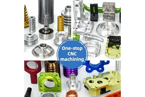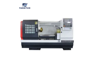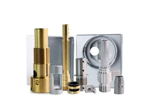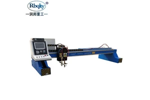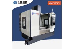
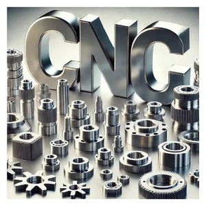
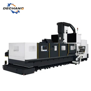
A Chucking Lathe produces rotational parts by turning the workpiece against a stationary tool, and modern versions add driven tools so milling and cross drilling are completed in the same cycle. Supplied to aerospace suppliers, this Chucking Lathe is configured with a bar feeder for continuous running. CNC turning with live tooling, steady rests and in-process gauging is carried out on equipment that holds ±0.01 mm across a full shift, not only on a first piece.
Tolerance is applied where it does work rather than across the whole drawing. Critical features are held to ±0.01 mm, non-critical dimensions follow the general machining tolerance, and the difference is stated in the quotation rather than discovered later.
Specification
| Process | Cnc turning with live tooling, steady rests and in-process gauging |
|---|---|
| Material / configuration | a bar feeder for continuous running |
| Size / capacity | turning length to 1000 mm |
| Tolerance | ±0.01 mm |
| Surface finish | turned finish, Ra 0.4–1.6 µm |
| Application | chucking lathe for aerospace suppliers |
| Inspection | Dimensional report, material certificate, first article report on request |
| Lead time | 7–15 working days for samples, 3–4 weeks for production |
| Minimum order | 1 piece for prototypes, from 50 pieces for production pricing |
Manufacturing process
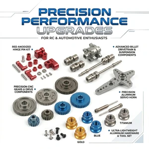
Work is carried out with CNC turning with live tooling, steady rests and in-process gauging. Tooling, speeds and fixturing are recorded with the part number, so a repeat order starts from a proven process instead of a fresh setup.
Material is purchased against a certificate and checked on receipt, so the composition is known before any cutting starts. Work in progress is identified by part number and operation, and the finished parts are deburred, cleaned and protected before they leave the machine area.
Typical applications
Most of the work supplied in this category falls into the following examples.
- Shafts and spindles.
- Flanges and couplings.
- Pulleys and rollers.
- Bushings and sleeves.
- Hydraulic cylinder components.
Quality control and documentation
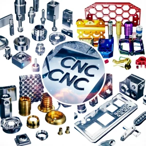
Critical features are measured on calibrated equipment in a controlled room, and the results are filed with the job so that a repeat order can be compared with the first.
Material certificates to EN 10204 3.1, dimensional reports and first article inspection reports are issued with the shipment where the application requires them. Calibration dates and measurement uncertainty are recorded alongside every result.
Ordering, lead time and packaging
Packaging is specified by the part: individual protection for finished surfaces, separation for assemblies, and export crating with a packing list for shipment.
Frequently asked questions
Can milled features be added without a second operation?
Yes, if the lathe has live tooling and a C-axis. Cross holes, flats, keyways and off-centre threads are then produced in the same clamping, which improves their relationship to the turned datums.
How is roundness held on long shafts?
With a steady rest or a tailstock, correct centre height and a final finishing pass. Between centres, concentricity within 0.02 mm over a metre is a normal expectation.
Can you supply material and inspection certificates?
Yes. Material certificates to EN 10204 3.1, full dimensional reports, first article inspection reports and, where required, PPAP or AS9102 documentation are issued with the shipment.
Drawings are reviewed for manufacturability before quotation, and any feature that adds cost without adding function is pointed out at that stage rather than after the parts are made.